Posted on 22 July 2023, by Kevin Mora
This is a summary of the paper "On the Mobility of All-Terrain Rovers", published by Giulio Reina and Mario Foglia in 2013.
Problem: The purpose of this writing was to help my team at NASA with the System Requirements Review (SRR) of a rover able to move in the Occator crater in Ceres. We know that a wheeled vehicle has trouble if the height of the object it must surmount approaches the radius of the wheels. In order to overcome this issue, an appropriate suspension system may be used.
About the use of springs: Springs mainly address drive comfort and control issues in vehicles that travel more than about 8 m/s. Below that speed, they are actually an impediment to mobility since they change the force each wheel exerts on the ground, as obstacles are negotiated.
Four-wheeled conventional independent suspension: This allows the vehicle to keep all wheels equally on the ground, but the wheels that are on the bumps, being lifted, are carrying more weight than the other wheels. One of the consequences specified in the paper is that this reduces the traction of the lightly loaded wheels. A better solution, at low speeds, is to allow some of the wheels to rise, relative to the chassis, over bumps without changing the weight distribution or changing it as little as possible. This objective can be achieved using a passive articulated suspension - a notable example is the so-called rocker-bogie suspension.
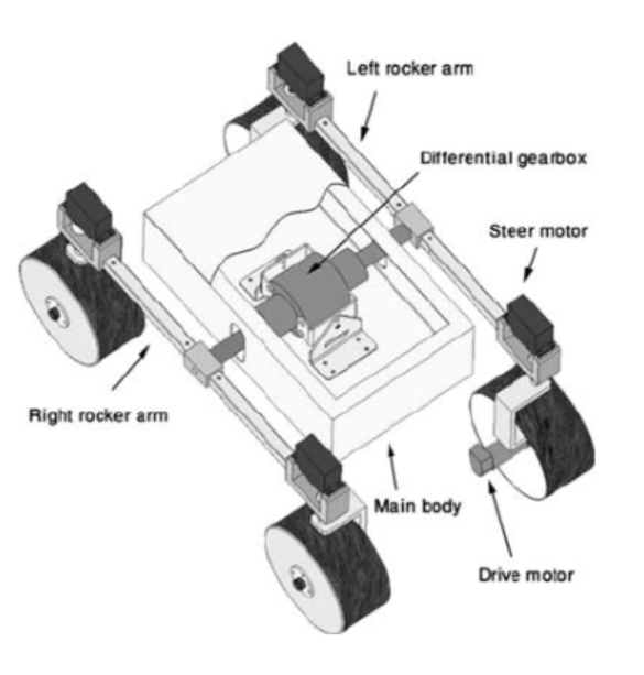
A four-wheel embodiment of the rocker-bogie suspension, usually simply referred to as rocker suspension, the drive wheels of either side of the vehicle are connected longitudinally by a rigid link, called rocker arm. Each one of the two rockers is pivoted to the main frame of the vehicle through the axis of a differential gearbox, whose input gear is attached to the chassis.
This configuration allows the rocker arms to pivot when any wheel tries to go higher or lower than the rest. The passive pivoting action keeps the load on all four wheels almost equal, increasing mobility simply by maintaining driving and braking action on all wheels at all times. Furthermore, the mechanical differential constrains the pitch angle of the chassis to be half of the pitch angle of either rocker.

Disadvantage of the rocker-type suspension: This type of suspension does not provide any compensation of wheel inclination angle relative to the ground in the transverse plane, i.e. the camber angle, during suspension travel. This causes the wheels to deviate from their optimal posture corresponding to a perfectly perpendicular configuration, as the robot adapts to terrain unevenness, thus reducing the traction performance and promoting undesired effects, such as wheel slip and sinkage, which greatly affect mobility. In addition, vehicle yaw may also be induced producing unpredictable deviations from the intended path. In principle, an upright wheel maximizes its footprint, reducing ground pressure and, therefore, sinkage in soft terrain. At the same time, the “grip” of the wheel, i.e. its ability to exchange forces with the ground, increases, thus reducing slippage.
Rover force analysis: This is another important aspect of the rover mobility prediction. The speed of autonomous vehicles is generally limited on rough terrain in order to avoid shocks and for safety reasons. Furthermore, the onboard computational burden is usually quite high (due for example to image processing, path planning or obstacle avoidance) whereas the available processing power is limited. This requires the rover to move slowly in a range of speeds (typically 5-20 cm/s) and accelerations (typically 0.05 - 0.1 percent of g) where the dynamic contributions can be neglected and a quasi-static model can be deemed appropriate.

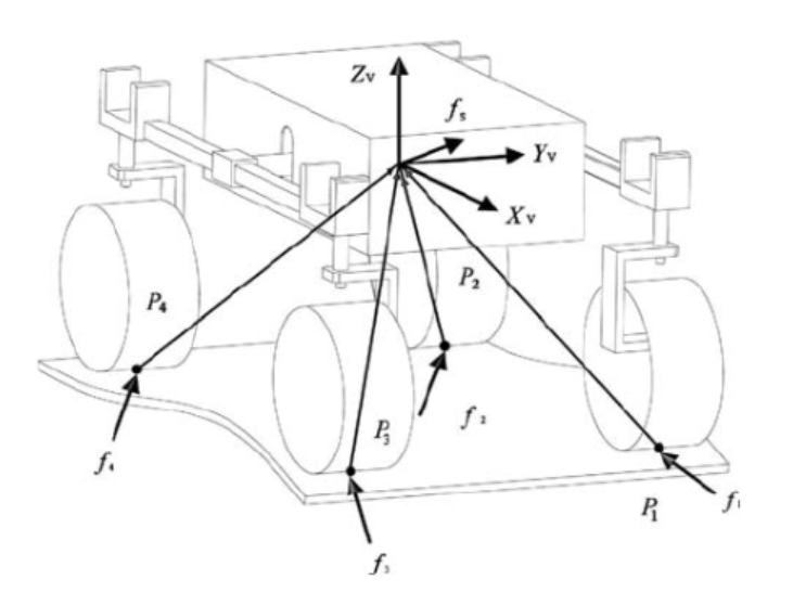
A set of quasi-static force balance equations for the rover above can be written as:
$$\begin{bmatrix} & I & & ... & & I & \\ 0 & -p_1^z & p_1^y & & 0 & -p_4^z & p_4^y \\ p_1^z & 0 & -p_1^x & ... & p_4^z & 0 & -p_4^x \\ -p_1^y & p_1^x & 0 & & -p_4^y & p_4^x & 0 \\ \end{bmatrix} \cdot \begin{bmatrix} f_1\\ ...\\ f_4\\ \end{bmatrix} = f_s$$As we keep reading, we find that a crucial problem for over-constrained rovers is that each wheel is controlled independently in a closed-loop manner. This results in one wheel speeding up while another wheel slowing down to get up to its speed set point under different loading profiles. One way to reduce slippage is that of minimizing the difference between the tractive efforts exchanged by the robot’s wheels with the ground.
| Rules of Thumb | |
|---|---|
| Drive Motor Torque | The higher the torque, the bigger the drive motor, which adds weight to the rover and consumes more energy. |
| Wheel Load Ratio | It is defined as the percentage ratio of the vertical load acting on a single wheel to the total weight force of the robot. Since the tractive thrust that a wheel can develop increases with its vertical load, the higher the load ratio, the larger its traction ability. |
| Friction Coefficient | The smaller the friction required by the vehicle for a given configuration, the better the climbing ability of the system. |
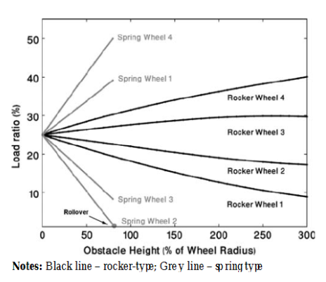
Note about the simulated wheels and their performance: The rock is modeled as a step-obstacle, which, however, represents a worst-case condition. The height of the rock is initially set as half of the wheel radius (h = 50 mm). The comparison is further extended by increasing progressively the height of the obstacle up to 300 percent of the wheel radius.
Results are shown in the figure below, where the change in the wheel load ratio is shown as a function of the obstacle height. The rocker suspension ensures a more even weight distribution. Even with an obstacle high one and half of the wheel diameter (h = 300 mm or 300 percent of wheel radius), all wheels still keep contact with the ground and Wheel 1, which results in the “lightest” wheel, retains almost half of its nominal traction ability.

More about the rocker-type suspension: This type also ensures a lower traction torque demand than the spring-type system. The rocker-type suspension provides a more uniform weight distribution, whereas, in the spring-type solution, climbing Wheel 1 and cross-coupled Wheel 3 are rapidly loaded, as Wheels 2 and 3 are unloaded accordingly. Thus, the better traction performance of the rocker type suspension is clearly demonstrated. The advantage of the rocker system is confirmed again, when considering the minimum friction coefficient required to traverse the obstacle.
In summary, conventional suspension systems greatly reduce the load and therefore the traction on wheels that are extended to lie below the level of the other wheels. The rocker avoids this by featuring a chassis supported on a central pivot, which ensures equal distribution of load on all wheels, and therefore equal traction on each wheel. If a stiff suspension system is used, the chassis will be considerably deflated when any one of the wheels is deflected. A reduction of weight shift may be achieved by using low rate springs. However, this solution would result in an undesirable low oscillation frequency, usually referred to as “too soft a suspension”.
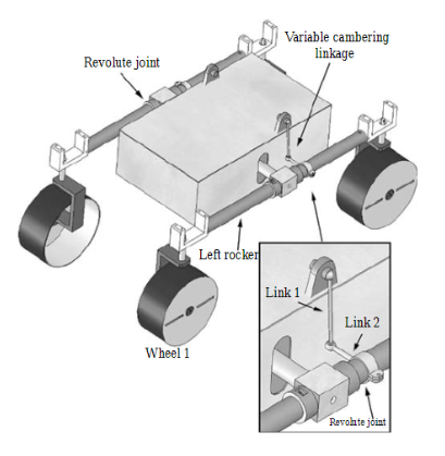
Critical drawback of rocker-type suspension: It does not provide any compensation for the change in the wheel camber angle during suspension travel. This results in a reduction in the overall traction performance of the rover as it conforms to irregular terrain. In this section, a variable camber mechanism is proposed that can be easily integrated with rocker-type suspension systems. The idea is to obtain an adaptive suspension that enables the robot wheels to adjust their inclination angle in order to hold a perpendicular posture with respect to the ground. This ensures that wheels operate at peak efficiency with a regular pressure distribution and a maximum footprint area at all times.
About the model proposed and the variable cambering mechanism: According to our model, the body of the robot tilts with a pitch and roll angle in absolute value of 11.5 and 8.58, respectively. It is apparent the undesired cambering of all four wheels. The contact patches are largely reduced, affecting the ability to exchange tangential forces with the ground, and, thus, to accelerate, brake, balance lateral loads, and climb obstacles. Therefore, a variable camber system, aiming to keep the wheels upright throughout suspension travels, would be greatly beneficial.
An innovative design of rocker suspension system is proposed that enables the wheels to modify their relative camber to contrast the effect of body roll and to maintain an optimal posture even on highly irregular terrain. This is achieved using a simple driving linkage, which controls the cambering motion of the wheels of the same side of the robot during relative rotations with respect to the chassis.
In order to maximize its footprint, each wheel needs to remain upright, perpendicular to the ground, as the suspension complies with terrain unevenness. The proposed mechanism fulfills the design requirement that the wheel gains a positive camber during its upward travel and a negative camber during downward travel.

The cambering mechanism would be beneficial even in presence of a not-leveled obstacle by keeping a suboptimal posture of the three not-climbing wheels.
An adaptive suspension system with wheel cambering compensation was also presented that can be integrated with rovers employing rocker-type suspensions, which seems like the best solution. The geometrical optimization of the variable cambering mechanism was discussed, aimed to keep wheels always perpendicular to the ground as the robot tilts adapting to ground unevenness.